Saturday, October 24, 2009

Sun VirtualBox

At a Glance

* Enterprise-class open source virtualization from the desktop to the server
* Handles massive workloads of up to 32 vCPUs
* Share and publish appliances with other virtualization platforms
* Runs multiple operating systems at once on one PC
* Enables cross-platform, multi-tier applications
* Supports the Solaris OS, OpenSolaris, Windows, Macintosh OS X, and Linux
* Provides remote access to guest virtual machines from anywhere
* Supports virtual server environments
* Protects hardware investment

See All Features
What's New

* Sun Microsystems Unveils VirtualBox 3.0 with Powerful New Server Virtualization Features
* Take Windows 7 for a Spin with VirtualBox
Computerworld's Vaughan-Nichols recommends fast and flexible VirtualBox for trying Windows 7 before deploying.
* Illuminata Research Report: Sun's Virtualization Strategies
Spotlights Sun's virtualization strategy and, in particular, VirtualBox and Sun virtualization software.
* Blueprint: Optimizing the desktop using Sun VirtualBox
Intro to Sun VirtualBox. Easily enable multiple virtual machines (VMs) on one desktop and access other operating systems in a native OS environment.


Thursday, October 22, 2009

4.6 C IDES installation procedure

4.6 C IDES installation procedure

Below is the 4.6 C IDES installation procedure.

Code

On Drive C:

1. Install Win2k server on
2. Install all drivers
3. Install IE6 SP1
4. Install Win2k SP4
5. Restart Computer

1. Modify network settings to use IP addr 192.168.1.27, add IPX, add NetBIOS
2. Increase Virtual Memory
3. Optimize file cashed for network apps
4. Add 192.168.1.27 srv1 SAPTRANSHOST
5. Create User - C11adm; Assign administrator privileges
6. Restart
7. Update DLL's from Kernal CD
8. Login as c11adm and continue installation

On Drive C:

1. Install oracle server+when listener config window pops up choose "typical config"
2. Stop all oracle services
3. Install oracle 8.1.7.1 hot fix for server – Manually copy folders see readme.txt after extracting sap81701srv.exe
4. Give all users access to ora_dba
5. Restart, login as c11adm and continue installation.

1. Install R3SETUP tool
2. Click R3SETUP.BAT on kernel CD (CD Drive:NTCommonR3setup.bat)
3. Install everything on drive E
4. logoff as per R3SETUP
5. logon as c11adm

1. Install Central Instance
2. Start>Programs>SAP system setup – install central instance
3. System name: C11
4. Instance: 00
5. domain:
6. transport host: SAPTRANSHOST
7. DB sys name: C11
8. DB inst host: srv1
9. Dir for SAP system: E:
10. Defaults for remaining entries
11. Location of kernel D:
12. Password 2X
13. Password 2X
14. SAP System Management Console will show up on desktop
15. Restart computer; login as c11adm.

1. Insert IDES CD1, copy D:IDESNTORADB_IDES.R3S to E:Usersc11admInstall.
2. Start>Programs>SAP System>Command file editor
3. Load DB_IDES.R3S, click install.
4. At 89% they will request a password for 'sapr3' pass word is 'sap'
5. At 94% you may need to start SAP in you SAPMMC then start the install up again
6. Import DOKCLUTX.EXT into database per IDES installation manual.

1. Once installation is complete upload SAP service packs
2. configure transports transaction ostms
3. Apply the latest SPAM/SAINT update
4. Apply service packs using transaction SPAM

Configure Transport Management System

Login as User DDIC
Password 19920706
/ostms
click on button transport routes (shift + F7)

Under Configuration status
Click on C11 (it is yellow)
Click on green check to activate it.

Tuesday, October 13, 2009

CISCO 2801 Router - Integrated Services for Small and Medium Business

Key Features of the Cisco 2801 Integrated Services Router:
  • Mid/High-Density, High Performance Services
    • Security: On-board encryption, up to 800 VPN tunnels (AIM); IOS FW, NAC, IPS, or Content Security
    • Voice: Mid/High-density analog/digital voice with IP Telephony, Voice Mail; CallManager Express or Survivable Remote Site Telephony support for up to 24 IP phones
  • High-performance concurrent security, voice and advanced services to multiple T1/E1 WAN rates
  • Integrated Dual 10/100 ports
  • Optional integration of L2 switching with PoE
  • Enhanced Modularity and Investment Protection
  • Flexible expansion ( 2 HWIC slots), additional concurrent services
  • Existing WIC/VIC/VWIC, AIM support
  • Scalable services deployment and availability features


Details Provided By Geez Technologies

CISCO Router commands

Router commands
Usermode Commands
Sl. No. Command Comments, if any.
1 disconnect Terminates the suspended telnet session and then logout it.
2 enable
3 ping Used to tests the connectivity.It uses ICMP to initiate the connection.
4 ping
5 traceroute Lists all routers along path to destination and finds the routing problems if any.
6 traceroute

Privilegemode Commands
Sl. No. Command Comments, if any.
1 clear arp-cache
2 configure terminal Allows to execute commands that change the router's configuration.
3 copy running-config startup-config It saves the active configuration of the router.
4 copy startup-config running-config
5 debug ip packet
6 disable Returns to the UserEXEC mode from Privilege mode.
7 disconnect
8 erase startup-config Deletes all the configuration files present on a router.
9 logout It exits router from the user or privilege mode.
10 ping Used to tests the connectivity.It uses ICMP to initiate the connection.
11 ping
12 reload
13 resume
14 show access-list Displays all accesslists from all protocols present in a specified router.
15 show banner
16 show cdp Shows the status of CDP such as holdtime value,no.of packets for every 60sec.
17 show cdp interface It tells the CDP configuration on an interface-by-interface basis.
18 show cdp neighbor
19 show cdp traffic
20 show clock
21 show flash Used to view all IOS images and file stored in flash(Default location of IOS images is in flash).
22 show frame-relay lmi Shows the detailed statistics regarding LMI.
23 show frame-relay map
24 show frame-relay pvc Shows all the frame relay PVC's terminated and their statistics at a specified router.
25 show history Shows the previously executed commands.IOS device stores the last ten commands that are executed.
26 show hosts
27 show interfaces To view interfaces,status,and statistics for an interface.If u don't lists a specific interface,all of the interfaces on the router are listed.
28 show interfaces ethernet 0
29 show interfaces loopback 0
30 show interfaces serial 0 displays the lmi type that is being used and also sme LMI statisstics.
31 show ip arp
32 show ip eigrp neighbors Shows the list of eigrp neighbors that a specified router has.
33 show ip eigrp neighbors detail
34 show ip eigrp topology Displays the list of successor and feasible successors,as well as other types of routes.
35 show ip eigrp traffic It shows the information about trafiic statistics for eigrp
36 show ip interface
37 show ip interface brief Verifies the IP configuration.
38 show ip ospf database
39 show ip ospf interface
40 show ip ospf neighbor detail
41 show ip route Verifies the configurationof static and default routes on a router.
42 show protocols Displays the routing protocols that have been configured and running on a specified router.
43 show running-config
44 show sessions shows the telnet sessions that are currently suspended.
45 show startup-config
46 show version Display version information for the hardware and firmware.
47 telnet
48 telnet
49 traceroute
50 traceroute Lists all routers along path to destination and finds the routing problems if any.
51 vlan database Used to access all VLAN and VTP configuration.
52 write erase
53 write memory
54 write terminal

Global configuration mode Commands
Sl. No. Command Comments, if any.
1 access-list {permit | deny} Only standard access list of the format given is supported.
2 access-list {permit | deny}
3 access-list {permit | deny}
4 access-list {permit | deny}
5 banner motd It creates the login banner on a specified router.
6 cdp advertise-v2
7 cdp holdtime
8 cdp run
9 cdp timer
10 config-register Hexadecimal or decimal value that represents the 16-bit configuration register value. It is used at the router start-up. The value range is from 0x0 to 0xFFFF (0 to 65535 in decimal). Normally, the default value is 0x2102
11 dialer-listprotocol ip permit
12 enable password Sets the paasword.The level number is either 1 or 15.
13 enable secret Encrypts the password when it is saved.
14 end
15 hostname
16 interface ethernet 0 Used to access ethernet interface and enter Interface subconfiguration mode.
17 interface fastethernet
18 interface loopback 0 Used to create loopback interface.Port numbers can specify between 0 to 2147483647.
19 interface serial 0
20 interface vlan
21 ip default-gateway Tells the router which router to use when the router needs to reach the destination thats not in its configured subnet.
22 ip default-network
23 ip domain-lookup
24 ip host Complete syntax for this command: ip host name [tcp-port-number] address1 [address2...address8]
25 ip name-server By using this Router access the DNS server to resolve the names to ip addresses.
26 ip route {next-hop-ip-addr | interface-type} The command supported by the simulator are:
ip route and
ip route serial
27 ip route 0.0.0.0 0.0.0.0
28 ip route
29 ip route serial 0 Not supported at this time
30 ip routing
31 ipx routing
32 isdn switch-type
33 line aux
34 line console 0 To enter into console interface.Here 0 specifies the console part.
35 line vty It supports 16 simultaneous telnet connections and each connection is internally tracked by a number:0-15.
36 no banner motd
37 no cdp run It can globally enable or disable the cdp on a router.
38 no ip domain-lookup It disables all the DNS lookups on the router.
39 no ip routing
40 no router eigrp
41 no router ospf
42 no router rip
43 no vlan
44 router eigrp
45 router ospf Process_id is locally significant and is used to differentiate different ospf processes running on a router.
46 router rip Enters into the RIP routing protocol configuration mode.
47 snmp-server enable traps vtp
48 username password


Interface subconfiguration mode Commands
Sl. No. Command Comments, if any.
1 bandwidth Required bandwidth, in kilobits per second.
2 cdp enable
3 clock rate Desired clock rate in bits per second: 1200, 2400, 4800, 9600, 19200, 38400, 56000, 64000 etc.
4 compress stac in
5 description Character string from 1 to 80 characters.
6 dialer-group
7 dialer map ip
8 dialer map ip name
9 dialer string< phone_#>
10 encapsulation Only PPP/HDLC are supported at this time by the simulator.
ex: encapsulation hdlc
11 encapsulation framerelay in
12 frame-relay lmi-type Specifies the LMI type that is used to communicate between a router and carrier's switch.LMI type is specific to the entire interface,not to a VC.
13 frame-relay map It configures the manual resolution of PVC's.
14 frame-relay map broadcast
15 frame-relay map broadcast cisco
16 frame-relay map broadcast ietf
17 frame-relay map cisco
18 frame-relay map ietf
19 ip access-group in
20 ip access-group out
21 ip address
22 isdn spid1 Defines the spid's that are used to authenticate call requests.Used only on local connection between router and isdn switch.
23 isdn spid2
24 keepalive
25 login
26 no bandwidth
27 no cdp enable
28 no clock rate
29 no frame map
30 no frame map broadcast
31 no frame map cisco
32 no frame map ietf
33 no ip address
34 no shutdown
35 shutdown It disable the interfaces.Interfaces are enabled by default.
36 shutdown switchport
37 speed
38 switchport access vlan
39 switchport port-security mac-address sticky
40 switchport port-security maximum
41 switchport port-security violation

Line subconfiguration mode Commands
Sl. No. Command Comments, if any.
1 exec-timeout [seconds] seconds is optional.
2 logging synchronous
3 password

Subinterface Subconfiguration mode Commands
Sl. No. Command Comments, if any.
1 discription It specifies the DLCI number.Uses a dynamic resolution with inverse ARP.
2 frame-relay interface-dlci It specifies the DLCI number.Uses a dynamic resolution with inverse ARP.
3 frame-relay map
4 frame-relay map broadcast
5 frame-relay map broadcast cisco
6 frame-relay map broadcast ietf
7 frame-relay map cisco
8 frame-relay map ietf
9 ip address
10 no ip address
11 no shutdown It specifies the DLCI number.Uses a dynamic resolution with inverse ARP.
12 shutdown It specifies the DLCI number.Uses a dynamic resolution with inverse ARP.

IP Routing Protocol Subconfiguration mode Commands
Sl. No. Command Comments, if any.
1 network Used with routing rip, igrp etc.

User mode Commands

Supported Switch Commands

Sl.No. commands Comments, if any.
1 enable

Privilegemode Commands
Sl.No. commands Comments, if any.
1 clock set hh:mm:ss <1-31> Month <2004-2035>
2 configure terminal Allows to execute commands that change the switch's configuration.
3 copy running-config startup-config It saves the active configuration of the switch.
4 copy startup-config running-config
5 disable Returns to the UserEXEC mode from Privilege mode.
6 erase startup-config
7 logout It exits switch from the user or privilege mode.
8 reload
9 show banner
10 show flash Used to view all IOS images and file stored in flash(Default location of IOS images is in flash).
11 show history
12 show interfaces To view interfaces,status,and statistics for an interface.If u don't lists a specific interface,all of the interfaces on the switch are listed.
13 show ip interface brief Verifies the IP configuration.
14 show running-config It examine the active configuration on a switch.
15 show startup-config
16 show version Display version information for the hardware and firmware


Global Configuration mode Commands
Sl.No. commands Comments, if any.
1 banner motd It creates the login banner on a specified router.
2 cdp advertise-v2
3 cdp holdtime
4 cdp run
5 cdp timer
6 enable password It sets the paasword.The level number is either 1 or 15.
7 enable secret Encrypts the password when it is saved.
8 end
9 hostname
10 ip default-gateway Tells the switch which router or switch have to use when the switch needs to reach the destination thats not in its configured subnet.
11 ip host
12 interface fastethernet <0-0>/<0-24> Depends on the switch type. For module 0, port 1 the command is interface fastethernet 0/1
13 interface vlan You can enter interface config mode.
example: interface vlan 1
(config-if)#ip address 192.168.10.1 255.255.255.0
14 line console 0
15 line vty 0 15
16 mac-address-table static vlan interface fastethernet
17 snmp-server enable traps vtp
18 speed Enter switch port speed 10,100, auto.


Interface Subconfiguration mode Commands
Sl.No. commands Comments, if any.
1 description
2 duplex
3 ip address A switch can have one IP address. The IP address of the switch can be accessed only through ports that belong to the management VLAN.
4 ip name-server
5 login
6 no ip address
7 no shutdown It reenables the interface when the interface is disabled.By default interfaces are enabled.
8 no switchport
9 shutdown Disables a port and shuts-down management vlan. no shutdown command enables a port.


Line Subconfiguration mode Commands
Sl.No. commands Comments, if any.
1 password


Vlan mode Commands
Sl.No. commands Comments, if any.
1 vlan VLAN numbers can range 1-1000,However only 64VLANs can be active ata time.
2 vtp client Specifies the VTP mode of the switch.
3 vtp domain Defines the domain name for a specified switch.For switches to share VTP informtion they must be in the same domain.
4 vtp password
5 vtp pruning
6 vtp server
7 vtp transparent


Workstation Commands
Sl. No. Command Comments, if any.
1 ip address
2 ping
3 ping
4 telnet
5 telnet
6 traceroute
7 traceroute

Friday, October 9, 2009

Windows Server 2003 to act as a NAT router

IP addresses were handed out to companies on an indiscriminant basis. As the popularity of the Internet increased, IP addresses soon grew to be a scarce commodity. Internet service providers began to strictly limit the number of IP addresses that they would lease to companies. This presented an interesting challenge. A PC has to have an IP address in order to communicate with the Internet, but there weren’t enough IP addresses left for every PC to be given one. The solution to this problem was a technology called Network Address Translation (NAT). Today, NAT is alive and well, and more popular than ever. In this article, I will explain what NAT is and how you can configure Windows Server 2003 to act as a NAT router.

So what is NAT? Network Address Translation, or NAT, is a technology that uses a router to share an Internet connection among the PCs on your private network, even though those PCs do not have a valid public IP address. There are both hardware and software NAT routers. In this particular situation, we will be configuring a Windows Server 2003 machine to act as a software based NAT router.
As you probably know, a router’s primary purpose is to regulate traffic flow between two networks, and a NAT router is no exception. The server that you will use as a NAT router must have two network interface cards (NICs) installed. One of these NICs will connect to the Internet and the other will connect to the private network. PCs on the private network will then send HTTP requests to the NAT server via the server’s private network connection. The server will then retransmit the request over the Internet on behalf of the client. When the requested Web site responds, the response is sent to the NAT server, which in turn forwards it to the client who made the original request. The client never communicates across the Internet directly.
IP Addressing Considerations
As I explained in the section above, a NAT router acts as a gateway between your private network and the Internet. The server that is acting as the NAT router must have two NICs. One of the NICs is connected to the Internet. This NIC must be assigned the IP address that was given to you by your Internet Service Provider.
The other NIC connects to your private network. As I mentioned, NAT does not expect you to have valid IP addresses on your private network. Instead, you are basically free to pick an address range at random. There is the off chance that the range that you pick might already be in use by a popular Web site, but I have only seen someone pick an address range that caused problems once. If you want to use an address range that is guaranteed not to interfere with anything on the Internet, you can use the 192.168.x.x address range.
After you pick an address range, I recommend setting up a DHCP server so that it will assign addresses from your chosen address range (the DHCP term for an address range is a scope) to the workstations on your network. You must however statically assign an address to the NIC on the NAT server that connects to your private network. For example, if you chose to use the address range 192.168.1.0 to 192.168.1.99, then you might consider assigning the address 192.168.1.0 to the NAT server. You could then use the 192.168.1.1 to 192.168.1.99 address block as your DHCP scope.
While you are configuring your DHCP server, there are a couple of other considerations that you need to make. As you may know, DHCP allows you to optionally assign a default gateway and a DNS server to workstations along with an IP address. When doing so, you must set the default gateway address to match the private network address that you assigned to your NAT server.
You have a few different options when choosing which DNS server address the DHCP server should assign to the workstations on your network. If you don’t have your own DNS server, then the best thing that you can do is to just use the IP address of your Internet service provider’s DNS server. If your network is running Active Directory though, then you already have a DNS server and you should use its address. It doesn’t matter if your DNS server is authoritative for your domain or not. Simply point the workstations to it. You can then set up a forwarder on the DNS Server so that any unresolved queries get forwarded to your ISP’s DNS server.
The advantage to pointing clients to your own DNS server rather than to your ISP’s DNS server is that doing so will provide your users with better performance. Your DNS server is local, so queries reach the server more quickly than they would reach a remote server. Furthermore, your DNS server has a built in cache so that popular Web sites do not have to be resolved each time a user visits them.
Setting Up NAT
Begin by selecting the Routing and Remote Access command from Windows’ Administrative Tools menu. When you do, Windows will display the Routing and Remote Access console. Locate your server (just below the Server Status). There should be a big red dot to the left of the server, indicating that the server is currently inactive. Now, right click on the server and select the Configure and Enable Routing and Remote Access command from the resulting shortcut menu. When you do, Windows will launch the Routing and Remote Access Server Setup Wizard.
Click Next to bypass the wizard’s Welcome screen. You will now see a screen that’s similar to the one that’s shown in Figure A. This screen allows you to select various configurations for Routing and Remote Access (RRAS). RRAS can be configured to do just about anything that you want, but Microsoft has included several templates to make the configuration process easier for common deployment types. Select the Network Address Translation (NAT) option and click Next.

Figure 1: Select the Network Address Translation (NAT) option and click Next
The next screen that you will see, shown in Figure B, is a rather important one to pay attention to. The screen gives you the choice of selecting a network interface that is connected to the external network (usually the Internet) or to select a demand dial interface. In case you are wondering, demand dial is a feature that allows Windows to establish a dial-up connection when ever external connectivity is needed. For the purpose of this article, I am assuming that you have a broadband connection to the Internet. Additionally, I am assuming that the NIC that the broadband connection comes in through has a static IP address assigned to it. You will have to select that network interface.

Figure 2: Select the NIC that connects the server to the outside world
Before you click Next, you should notice that there is a check box that allows you to enable a firewall for the connection. I recommend always selecting this option. The firewall will keep unwanted traffic out of your network. If you need to grant external users access to some service on your network, you have the option of configuring port forwarding to pass packets through the firewall to the desired network resource.
After you enable the RRAS firewall, click Next and you will see a screen asking you to select the network that will have shared Internet access. Although the dialog box uses some weird wording, it is basically just asking you to select the NIC that is attached to your private network. Make your selection, and click Next, followed by Finish to complete the process.
Conclusion
In this article, I have explained how you can use a NAT server as a way of sharing an Internet connection among the users on your network. I then went on to explain how IP addressing should be configured and how to configure RRAS to act as a NAT router.

Designing Group Policy in an Active Directory environment

If you’ve implemented your sites, domains and OUs in the wrong way, Group Policy will be difficult to use and troubleshoot. So the first step in planning how you’re going to implement Group Policy on your network is to plan how you’re going to implement Active Directory itself. Such planning includes decisions like: How many forests you will deploy (one or several)? How many domain trees? Will there be child domains? What kind of OU structure will each domain have? And so on. Each of these decisions should always be made by asking the question: What impact will my decision have on how Group Policy is implemented in my enterprise? Let’s look at some guidelines that can help you design Active Directory effectively as far as Group Policy is concerned.
K.I.S.S.
The first and obvious principle is to “Keep It Simple, Stupid!” or “K.I.S.S.” In the context of Group Policy planning, this means two things:
If a single domain will meet all your company’s needs, then use only one domain. The reason simply is that the number of Group Policy Objects (GPOs) you will need to create is roughly proportional to the number of domains you have in your forest. For while linking a GPO residing in one domain to a container (domain, site or OU) in a different domain does reduce the total number of GPOs you need to deploy, it can have a significant performance impact and shouldn’t generally be done.
Keep your OU structure relatively simple, for example two or three levels of OUs at most. The reason is similar here to why you should keep your number of domains as low as possible: administrative overhead.
So let’s say you begin your Active Directory design by deciding you’re going to us a single domain (see Figure 1) with two or maybe three levels of OUs within it. That’s a good place to start. What’s next?

Figure 1: Have only one domain if possible
Server OUs
Group Policy isn’t just for managing desktops; it’s also terrific for locking down servers to ensure they’re secure and working properly. And by servers I mean both member servers (which include file servers, print servers, web servers, DHCP servers, and so on) and domain controllers. The best way to lock down domain controllers is to leave them in the default Domain Controllers OU and configure a GPO linked to that OU. There are two ways you can do this:
Configure the settings in the Default Domain Controllers Policy.
Create a new GPO, link it to the Domain Controllers OU, and configure it.
Which approach is better? Some experts recommend leaving the default GPO untouched and creating a new GPO and moving it to the top of the link order for GPOs linked to the OU. That way if something goes wrong later you at least have your default GPO in place and untouched. On the other hand, if you run the new Security Configuration Wizard (SCW) of Windows Server 2003 Service Pack 1 on a domain controller, then in addition to other changes it will modify certain settings in the Default Domain Controllers Policy to make your domain controller more secure. So either approach works fine, but personally I prefer the second approach.
What about your member servers? The trick here is to realize that the different member server roles are basically incrementally different from a baseline (having no role) member server. So a good approach is to create a top-level Member Servers OU and then beneath it add additional OUs for each role (Figure 2):

Figure 2: OU structure for member servers.
The advantage of this approach is that you can now create a baseline Member Servers GPO that generally secures any member server and link it to the Member Servers OU. That way all of the member servers in child OUs will automatically inherit this policy. Then you can create a Print Servers GPO and link it to the Print Servers OU, a File Servers GPO and link it to the File Servers OU, and so on. These different GPOs linked to child OUs of the Member Server OU can be used to incrementally harden security for each server role over the basic hardening provided by the Member Servers GPO.
Here’s a tip: if you want to find out more about using the above approach to harden servers using Group Policy, read the Windows Server 2003 Security Guide which is available from the Microsoft Download Center. This Guide has terrific suggestions on how to secure different server roles and it’s well worth plowing through its almost 300 pages of content. If you don’t have time to read the whole Guide, check out my blog ITreader.net and click Group Policy under Topics and you’ll find lots of useful information that I’ve culled from my own reading of the Guide as well as other Microsoft resources.
Desktop and User OUs
The OU structure you plan for your domain can depend on various things including your company org chart, branch offices, number of departments, and so on. There’s no hard and fast single best way of designing OUs for a domain, but the following tips can help you avoid problems later on when you start creating GPOs to lock down users and their desktop computers.
First off, you should only create an OU if there is some compelling reason for it to exist. For example, if users in the Sales, Marketing, and Reference departments all have similar needs as far as security goes, group their accounts into a single OU instead of three. Then if Sales users have some minor difference in security requirements from the other two departments, you can create and link another GPO to the OU and use security filtering to ensure only members of the Sales group have that GPO setting applied to them.
Next, you should try to create your OUs along departmental lines rather than geographical location. That way you can make more effective use of delegation when you need to use it. If you must have geographical OUs, make them the top-level OUs and then create child OUs beneath them for each division or department (Figure 3):

Figure 3: A typical OU structure.
Next, create separate OUs for computer accounts and user accounts (Figure 4). That way you can use separate OUs to lock down machine settings and user settings. Of course, you could achieve the same thing by lumping together computer and user accounts into a single OU, linking two GPOs to that OU, and disabling the machine settings in one OU and the user settings in the other OU. But keeping your computer and user accounts in separate OUs will make it easier for you to troubleshoot when Group Policy doesn’t do what you expected, and it makes mistakes in configuring policy less likely also.

Figure 4: Use separate OUs for computer and user accounts.
Also, try to avoid using Blocking, Enforced, Loopback, and other ways of modifying the default Group Policy inheritance order. That’s because using these features can make it really hard to troubleshoot why Group Policy isn’t doing what you intend it to do. If you find you absolutely must use these features in your Group Policy design, you probably haven’t designed your Active Directory structure very well. The one exception to this rule is security filtering, which is a powerful tool that can help make GPO targeting more accurate without complicating the design. I’ll cover security filtering in a future article on WindowsNetworking.com.
Finally, avoid making changes to the Default Domain Policy. Instead, create a new GPO, link it to the domain, and configure its settings as needed. But be very careful what you configure in any GPO linked to a domain because any settings you configure will be inherited by all computer and user accounts in all OUs in the domain. So the moral is, wherever possible configure policy at the OU level and not at the domain level, and use domain GPOs only for configuring account policy for the domain.

Windows 2003: Data Backup and Recovery

The loss of data can bring an enterprise down – be it for a few hours, days, or even weeks. For smaller businesses, data loss can be devastating. For home users, it can be heart-breaking and utterly annoying. Whatever brings about data loss is bound to cause an organization to suffer – not only from the loss of the data itself but from loss in employee productivity during the time it takes to restore information from a backup set. Having said this, it becomes clear that backup is, without a doubt, one of the most significant aspects of a business continuity plan.
Essentially the term “backup” means a duplicate copy of key information, both physical (paper) and computer records. An organization must create a decent set of backup procedures to ensure that data is protected, and then follow them to a Tee.
Vital paper records that should be stored safely include tax records, financial statements, contracts, personnel information, and corporate documents. Data that should be backed up regularly includes, but is not limited to, e-mail correspondence, audit files, user information, utilities and applications, operating systems, financial data and databases, as well as customer lists. Ideally every byte of data on every system in an organization would be backed up every night. In today’s world this is not a realistic possibility – due to a lack of time and resources. These days, you are obliged to choose what will or won’t be backed up, based on the importance of the data.
Planning for Backup and Recovery
When planning for backup and recovery, you must ask yourself a number of questions to help you make a decision on how, when and what data will be backed up. These include the following:
When is the most convenient time to schedule backups?
Backing up data should ideally be done at off-peak hours when system usage is low. However, due to the type of data being backed up this is not always possible. Considerations must be made as to when key system data is to be backed up.
Will you store backups off-site?
It is highly recommended that backup media (containing data) is stored off-site in case of a natural disaster, fire, leak, etc. It would also be wise to keep a copy of the software required to install and restore operating systems, database servers, backup recovery, and so on.
How important is the data your systems contain?
Classifying the importance of your data will help you decide if the data needs to be backed up, how it should be backed up and when it should be backed up. Critical data (such as financial data, databases, etc) will take priority and should have a long-term redundant backup set, whereas data of less importance should be backed up daily and easily be recoverable.
How fast will restoring data from backup need to be?
Bringing a critical system back online would normally be done as soon as possible. Your backup plan depends a lot on the time it takes to recover a system. Data should be classified by priority and restored in sequence.
How regularly does data change?
Data that changes daily should be backed up daily. The rate at which your data changes will reflect your decision on how often the data should be backed up.
What type of information does the data residing on the systems contain?
As well as knowing what information the data contains so that you can identify it as critical, confidential, etc, it’s important to note that although data may not seem important to you, it might be to someone else. This will help you determine when and how certain data should be backed up.
Do you have what’s necessary to perform backups?
Make sure that you have the right hardware and enough media needed to perform a backup. Choosing backup media is an important factor in the backup and recovery process. Backup tapes are a common form of media since they can store large amounts of data and are cheap. They are however much slower than alternative options.
Types of Backup
Each file or folder on your system consists of what is called an Archive attribute. If this attribute is enabled then the file or folder may require backing up at the next backup time.
To view the archive attribute in Windows 2003, right click a file or folder and select properties. Press the Advanced button to bring up the Advanced Attributes dialog box. This will allow you to select whether you want the object to be ready for archiving.
There are five backup types which you can use depending on the importance of the data you are backing up and how convenient you want the restoration process to be.
Daily
Backs up files that have changed since the last daily backup. If a file is modified on the same day as the backup, it will be backed up. The archive attribute of the files is not changed.
Incremental
Backs up files that have changed since the most recent full (normal) or incremental backup. If the archive attribute is present then it means the file has been modified – only files with this attribute are backed up. Once the file has been backed up, the archive attribute is cleared and only set once the data has been modified again.
Full (Normal)
Backs up all files that have been selected, despite the archive attribute setting. Once the file has been backed up, the archive attribute is cleared until the file is modified. When the archive attribute is set again, it indicates that the file needs to be backed up.
Differential
Backs up files that have changed since the last Full backup. If the archive attribute is present, it means that the data has been modified and files having this attribute set will be backed up. However, in this case the attribute is not cleared so as to allow other types of backups to take place on this data at a later stage.
Copy
Backs up all files that have been selected, despite the archive attribute setting. The archive attribute is not changed, so that other types of backup can be performed on the same data.
Keep in mind:
A backup procedure is never considered complete until it has been fully tested. What good is it if you backup data but can’t restore it?
Types of Backup Media
The most common types of backup media available on the market today include:
Tape drives
Tape drives are the most common backup media around due to their low cost. The average capacity of a tape drive is 4 to 10 GB. The drawbacks are that they are relatively slow when compared with other media, and can tend to be unreliable. Magnetic tape cartridges are used to store the data, which leaves it susceptible to loss of information over time or through breaking/stretching the tape.
Disk drives
Disk drives are expensive but very fast compare to tape drives. The disk drive rotates at a very fast pace and has one or more heads that read and write data. If an organization is looking for a fast method of backup and recovery then disk drives are the way to go – the difference in speed between a tape drive and a disk drive is hours compared to minutes, respectively.
Removable Disks
Using a removable disk such as a ZIP/JAZ drive is becoming increasingly popular for the backup of single systems. They are quite fast, not that expensive and easy to install and carry around. The downside is that the capacity is usually (at the time of writing this article) not more than 2GB in size.

Disk Quotas in Windows 2003

In this article we will look at what disk quotas are, when they should be used, and how to configure them in Windows 2003.

Windows NT Disk Quotas didn’t exist, which was much to the disappointment of Windows Administrators. Along came Windows 2000 and with the introduction of Disk Quotas it meant Administrators had the ability to track and control user disk usage. The only problem was that they didn’t really have a sufficient way of managing disk quotas. Scripting, reporting and remote usage methods were somewhat limited and ambiguous. Windows 2003 offers better all round functionality and easier enterprise-wide disk quota manageability.
Disk quotas are used in conjunction with NTFS, Group Policy and Active Directory technology. NTFS is the file system on which disk quotas can be set, Group Policy is what is used to set disk quotas on a specific set of users and computers, and Active Directory is used to gather a list of users to which the disk quota group policy will be set. It is important to note that disk quotas can only be used with NTFS; setting them up on FAT or FAT32 drives is not possible.
Disk quotas are configured on a per volume basis and cannot be set on a file or folder level. Each volume would have its individual settings which do not affect any other volumes. You may have a single disk partitioned into two volumes (drives C and D for example) with each having their own quota settings. Disk quotas can also be configured on a per user basis and different groups of users can have different limits set. Administrators are the only ones to whom a disk quota does not apply; by default there are no limits for an Administrator.
There are numerous reasons you may wish to make use of disk quotas. Based on the requirements of your organization you might choose to configure disk quotas if you have a restricted amount of disk space on a specific server, a limited number of servers, or perhaps the need to monitor user disk space usage without actually enforcing a quota. You might be wondering why you’d want to just monitor user disk space usage. Well, let’s say you have a fileserver set up with multiple users in your organization using it everyday to store temporary files. As time goes by and perhaps people forget to delete the files from the server, the amount of available disk space will continue to decrease. If nothing is done about it then users will be denied the right to add more files on the server (until some old files are removed). By monitoring user disk space usage with Microsoft’s disk quotas, you can be notified of when space is running out and then increase the allocated space on the server accordingly or notify your users that they need to delete their files from the server. Additionally, setting a quota warning level will allow for a system event log to be written for your review.
Setting a Group Policy
The most practical means of configuring disk quotas on a large scale would be through a domain-level group policy. This will configure the settings automatically on any of the volumes you wish to have disk quotas enabled, saving you the need to have to configure each volume independently.
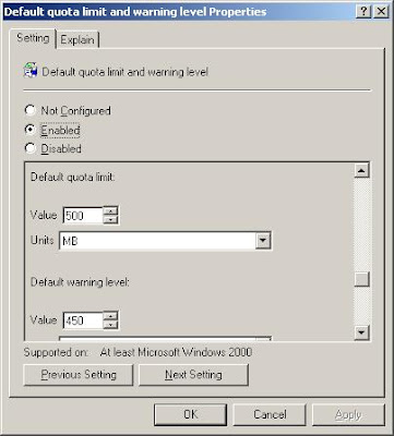
Open the Group Policy Object Editor (gpedit.msc) and navigate to Computer Configuration > Administrative Templates > System > Disk Quotas. On the right hand pane you will see a list of policies that can be applied. Double click the “Default Quota Limit and Warning Level Properties” setting.


Figure 1: The Default Quota Limit and Warning Level Properties Dialog
The default quota limit is the maximum amount of space assigned per default quota, whereas the warning level is the amount of space at which a warning is triggered. Normally 90-95% of the total value is a good limit to set as a warning.
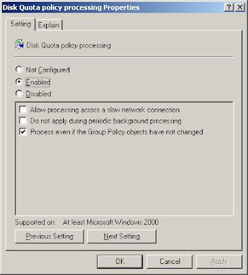
Now configure any other settings you wish to be applied by selecting them from the right hand pane. To have your changes applied immediately you can enable the “Disk Quota Policy Processing” policy and choose “Process Even If The Group Policy Objects Have Not Changed” from Administrative Templates > System > Group Policy.

Figure 2: The Disk Quota Policy Processing Dialog
You may also want to manually force a group policy update using the gpupdate utility. Simply go to Start > Run and type gpupdate followed by the return key. This will refresh both the computer and user policies.
Whatever changes you make in the group policy will be reflected on the Quota properties tab of each volume you wish to configure in your domain. The options will appear grayed out and non-editable.
Configuring Disk Quotas and Disk Quota Entries
Using the Computer Management console, you can configure disk quotas for a local or remote volume from a central location. To open Computer Management, you have three choices; either right click My Computer and select Manage, type compmgmt.msc in the Run bar or select Computer Management from the Administrative Tools folder.
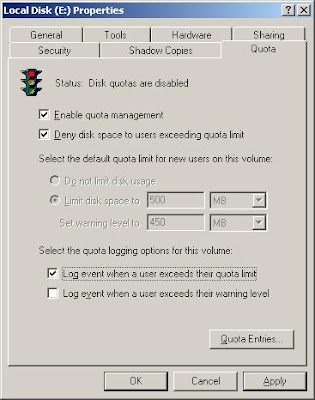
Select which computer you wish to manage from the root node. To select a remote machine right click the “Computer Management” node, select “Connect to another computer…” and choose the computer you wish to manage. Now, navigate to Storage > Disk Management and select the volume you want to configure from the right hand pane and open the properties dialog. Click the Quota tab and enable the options you want to be enforced.


Figure 3: The Disk Quota Properties Dialog
The traffic lights icon at the top indicate the status of the disk quota; red means quotas are disabled, orange signifies a changeover is taking place (while it rebuilds the disk information), and green means disk quotas are enabled. A textual representation of the status is shown on the right of the image.
Check “Deny disk space to users exceeding quota limit” to have Windows restrict users from adding more data to their allocated disk space when the quota limit has been reached. Users will be unable to add more data until some space is freed up.
As you can see from Figure 3 above, the quota limit for new users is greyed out. This is because we have already set it from the group policy, which overrides any customizable settings on the quota tab of a volume. In this case we have limited the user’s disk space to 500MB and set a warning level to 450MB.
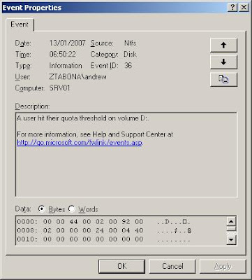
You may choose not to limit disk usage and just enable quotas to track disk space usage on a per volume basis by leaving the “Deny disk space to users exceeding quota limit” checkbox unchecked and logging a warning when a user exceeds the warning level defined as part of the quota limit. Whenever a user exceeds this limit a Warning event log will be written to the Application Event Log and shown in the Event Viewer.

Figure 4: A warning event log for disk quotas
As per http://support.microsoft.com/kb/915182 there is a known issue in the pre service pack version of Windows 2003 in that the Warning event log is incorrectly shown as an Information log in Event Viewer. In the Quota Entries application however, it is correctly displayed as a Warning.
When you press the Apply button on the Disk Quota Properties Dialog you are notified that the volume will be rescanned to update the statistics and that this operation may take several minutes. Simply press OK to continue and have disk quotas enabled on that volume.
Quota Entries
Click the Quota Entries button on the Disk Quota Properties Dialog to view a list of individual disk quota entries. From this section you can create, delete and manage quota entries for specific users or groups. If a user requires more space than others then you can set this from here.
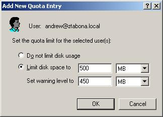
Go to Quota > New Quota Entry and the Active Directory User Picker will appear. Choose a user from Active Directory and press OK. You will be given the option to limit disk space and set a warning level or not limit disk usage at all.

Figure 5: Adding a new quota entry
Once you have chosen your preferred settings, press OK and the user will be added to the list. You can monitor a user’s disk usage by looking at the properties of each of the columns. ‘Status’ indicates whether the user is within their limit, if a warning has been logged or if the limit has been exceeded; the icon will change accordingly.

Figure 6: Viewing a list of Quota Entries